Assembly hints
Note that the device shown in most of these pictures is the Nokia Lumia Icon. On those steps the spare parts and the assembly procedures are the same.
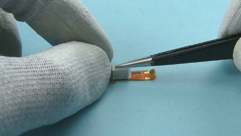
1) To assemble the PRIMARY MIC FLEX, first place the PRIMARY MIC GASKET on the microphone. Make sure the shown hole aligns with the microphone hole.
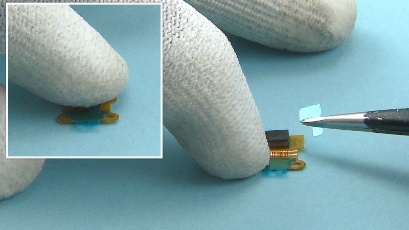
2) Press gently to activate the adhesive and remove the protective film from the PRIMARY MIC GASKET.
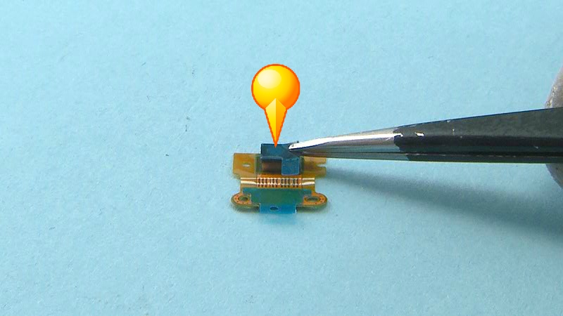
3) Remove also the protective film from the PRIMARY MIC FLEX.
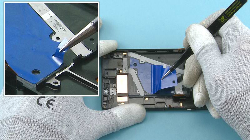
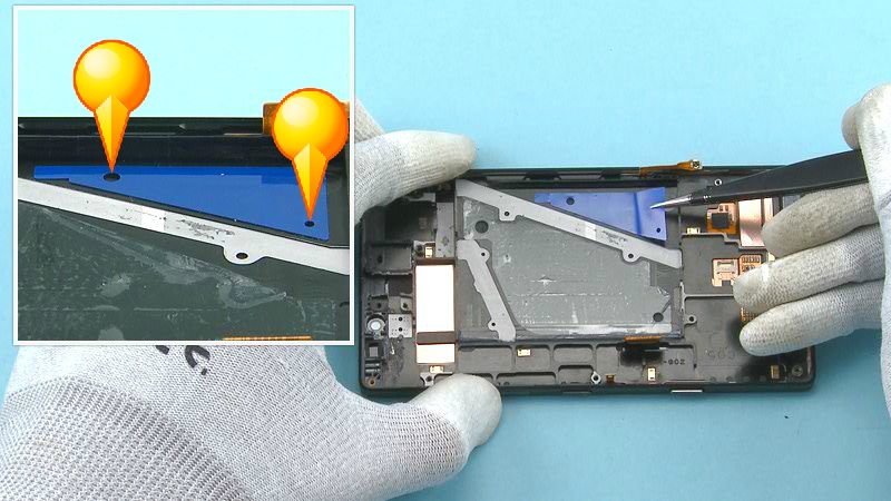
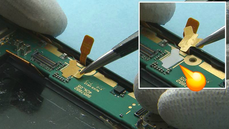
4) Place the PRIMARY MIC FLEX ADHESIVE to its slot in the UI ASSEMBLY. Use the shown holes to get the right alignment.
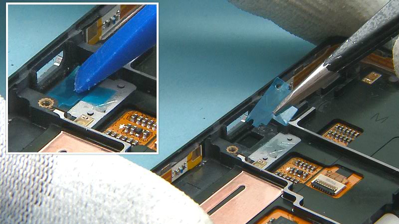
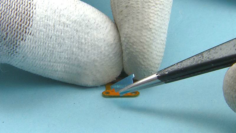
5) Press gently with the SS-93 to activate the adhesive and peel off the protective film.
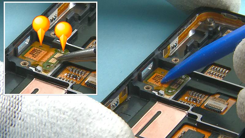
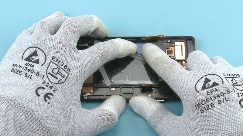
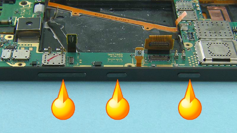
6) Place the PRIMARY MIC FLEX to its place. Use the holes to get the right alignment. Press gently to activate the adhesive.
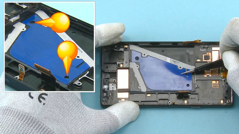
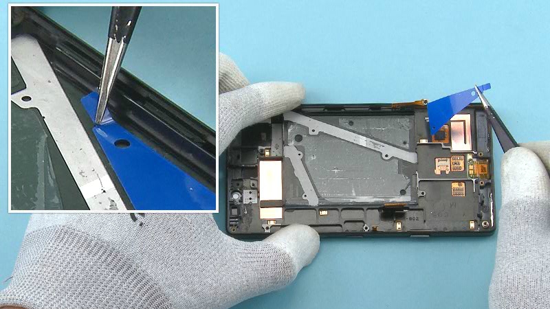
7) Place the BATTERY ADHESIVE as shown on the UI ASSEMBLY. Use the shown holes to get the right alignment.
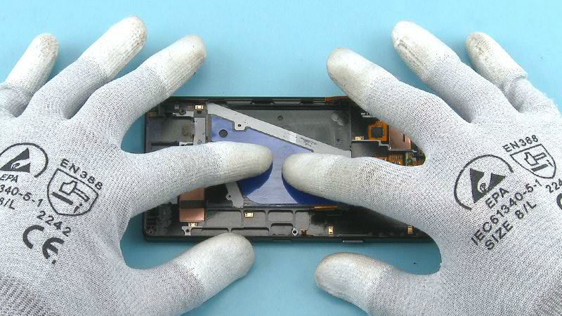
8) Press all around the ADHESIVE...
9) ... and peel off the protective film.
10) Place the SMALL BATTERY ADHESIVE as shown on the UI ASSEMBLY. Use the shown holes to get the right alignment.
11) Press all around the ADHESIVE...
12) ... and peel off the protective film.
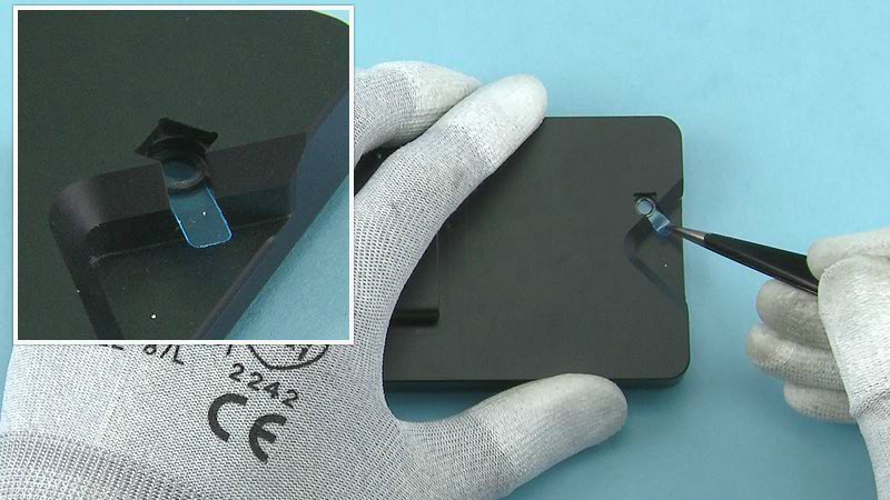
13) Start assembling the VIBRA ASSEMBLY by first placing the VIBRA BOOT on it as shown.
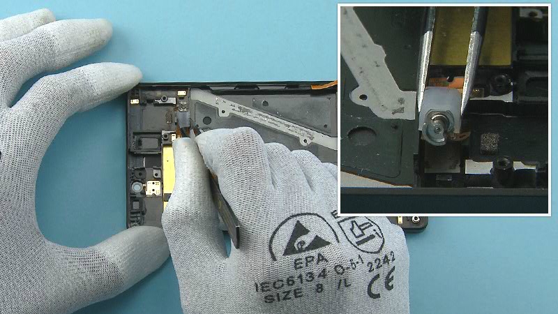
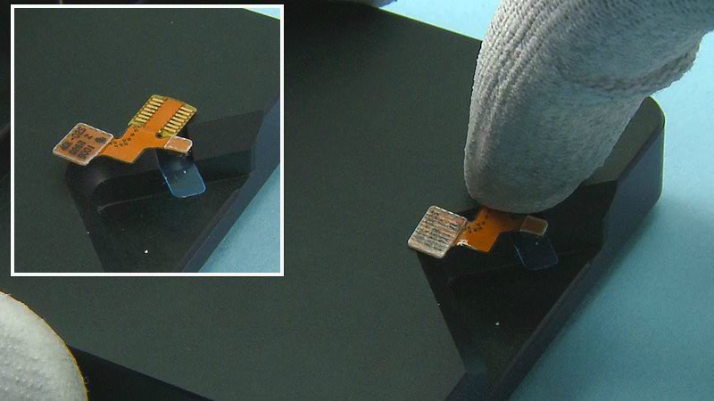
14) Place the VIBRA ASSEMBLY to its slot on the UI ASSEMBLY. First align the flex to its place, then lower down the VIBRA.
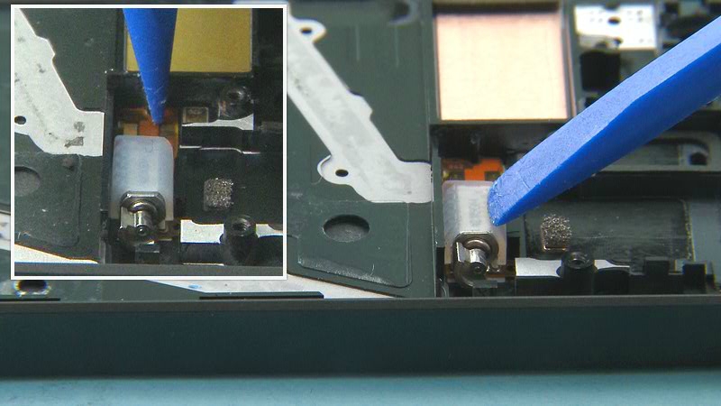
15) Gently press the flex and the VIBRA from the shown place to activate the adhesive.
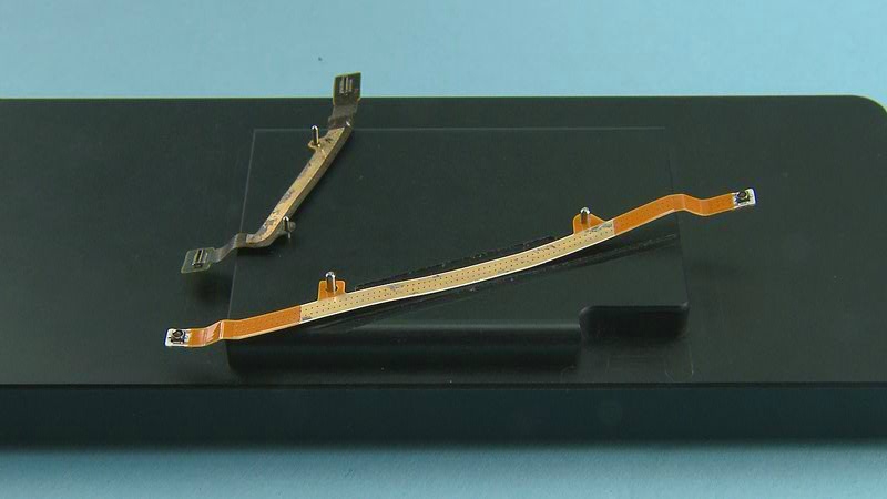
16) To assemble the MIMO COAX FLEX and the JUMPER FLEX, first place them on the SS-327 flex assembly jig. Use the guiding pins to get the right placement.
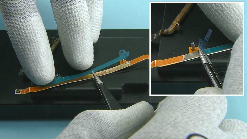
17) Place the MIMO COAX FLEX ADHESIVE on the MIMO COAX FLEX. Press firmly to activate the adhesive and remove the protective film.
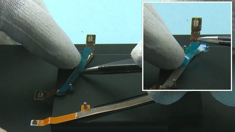
18) Place the JUMPER FLEX ADHESIVE on the JUMPER FLEX. Press firmly and remove the protective film.
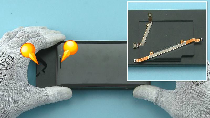
19) Before placing the UI ASSEMBLY on the jig check once more that the flexes are positioned on the jig as shown. Check also that the top side of the UI ASSEMBLY is facing the shown side of the jig as shown.
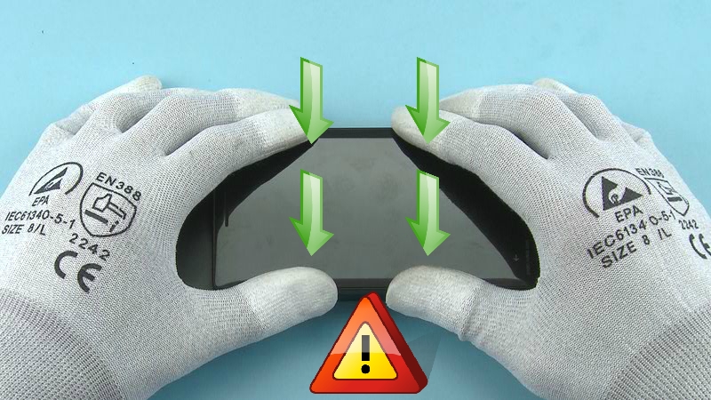
20) Then place the UI ASSEMBLY on the jig and press it gently but properly to get the flexes attached. Be careful not to damage the DISPLAY.
21) Remove the UI ASSEMBLY from the jig and check that the flexes are properly attached.
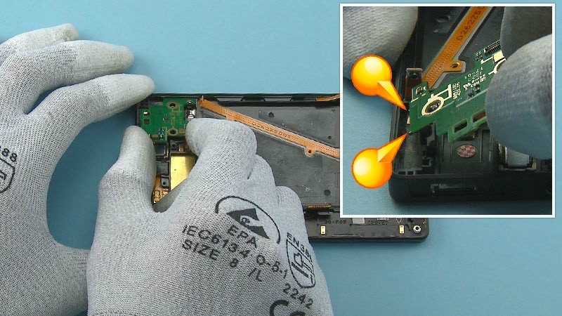
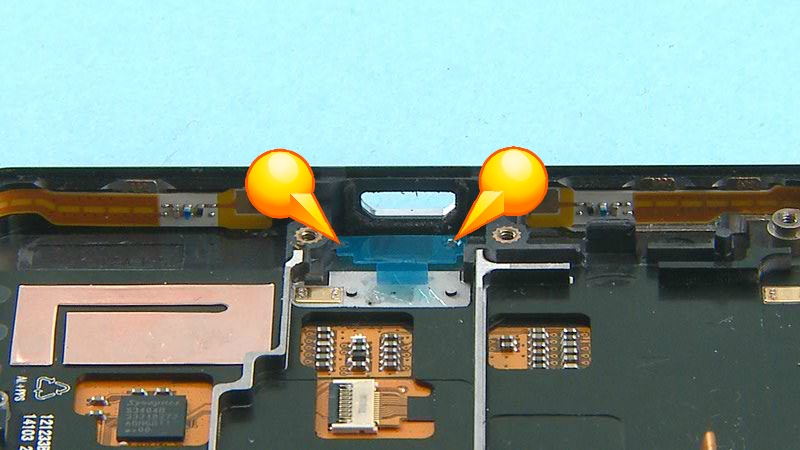
22) Assemble the DAUGHTER ENGINE BOARD to the UI ASSEMBLY shown side first. Align the two shown pogo pins to their places.
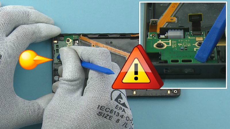
23) Then lower down the DAUGHTER ENGINE BOARD and press down to attach the shown clip. Be careful not to damage the DAUGHTER ENGINE BOARD or any of its componets.
24) When assembling the CAMERA use the SS-327 flex assembly jig as a steady platform.
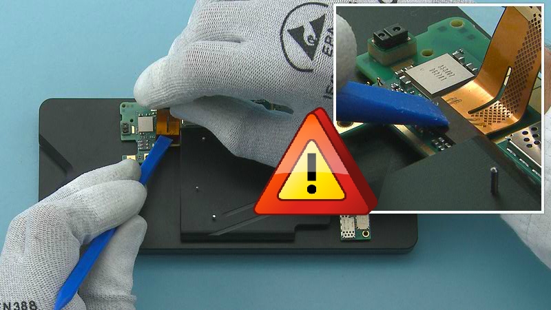
25) Connect the CAMERA to the ENGINE BOARD with the SS-93. Be careful not to damage the connector or any components nearby.
26) Then fold the CAMERA flex as shown.
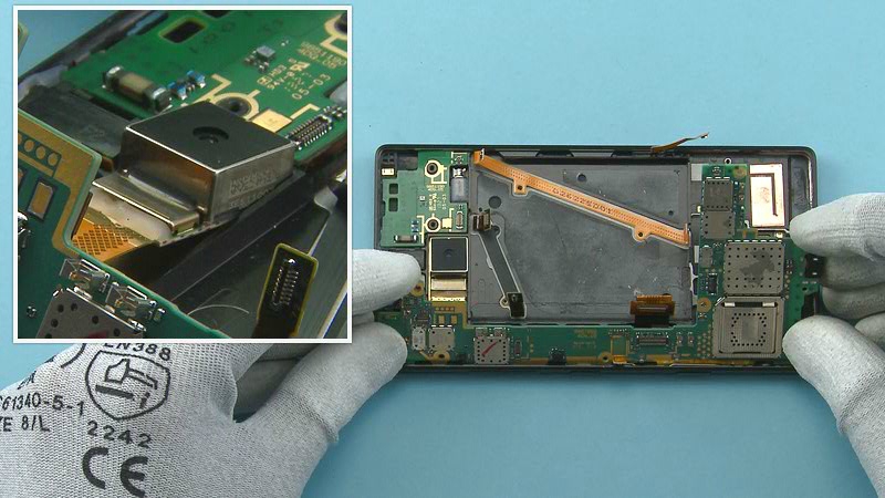
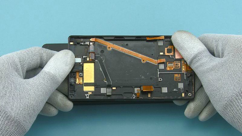
27) Start assembling the ENGINE BOARD to the UI ASSEMBLY shown side first and align the CAMERA to its socket.
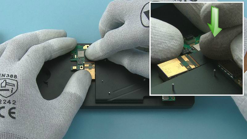
28) Lower down the ENGINE BOARD and press to attach the shown clip.
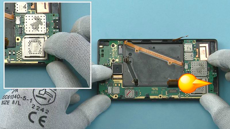
29) After assembling the ENGINE BOARD check the tactility of the side keys.
30) Place the LTE ADHESIVE to its place. Use the guiding lines on the ENGINE BOARD to get the right placement. Remove the protective film from the LTE ADHESIVE.
31) Place the SKYPE CAMERA GASKET to the shown slot on the SS-327 jig.
32) Place the SKYPE CAMERA on top of the gasket as shown and press it gently to activate the adhesive.
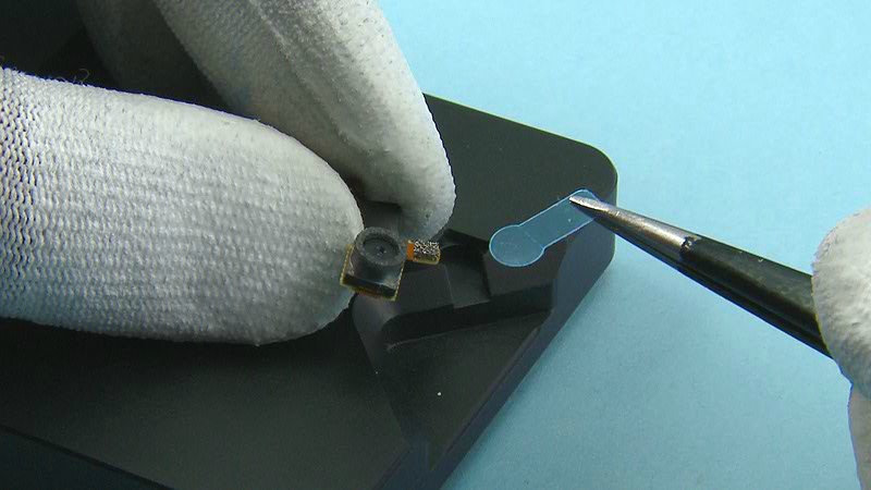
33) Remove the SKYPE CAMERA fom the jig and remove the protective film from the SKYPE CAMERA GASKET.
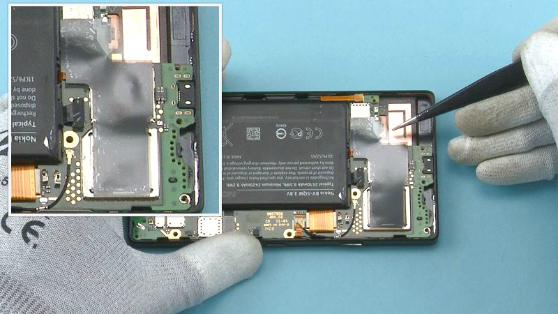
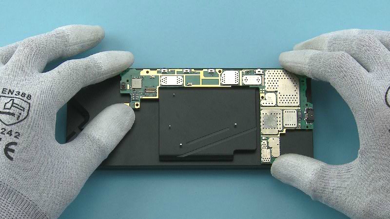
34) Place the HEAT SPREADER on the ENGINE BOARD as shown. Use the edges of the shielding lids to get the right alignment.
35) Press all around the HEAT SPREADER to activate the adhesive.
36) Remove the protective film and gently press all around the HEAT SPREADER again to make sure its properly attached.
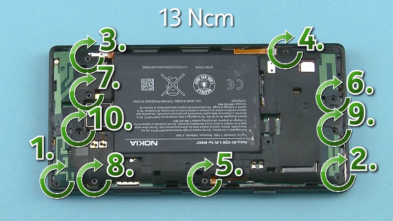
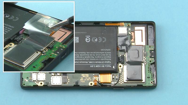
37) Fasten the ten TORX+ SIZE 4 screws in the order shown to the torque of 13 Ncm.
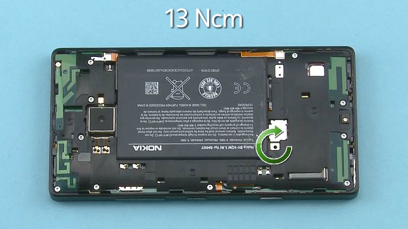
38) Fasten the TORX+ SIZE 4 screw to the top of the BATTERY CONNECTOR STRAP to the torque of 13 Ncm.
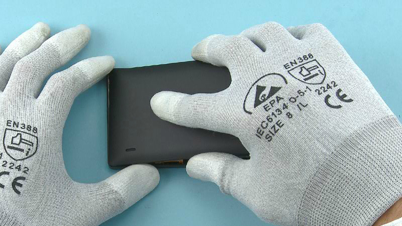
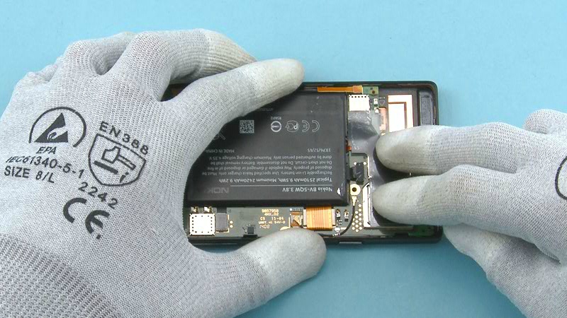
39) Assemble the BACK COVER to the UI ASSEMBLY bottom end first.
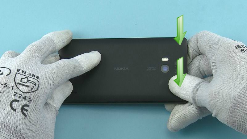
40) Press together the top end.
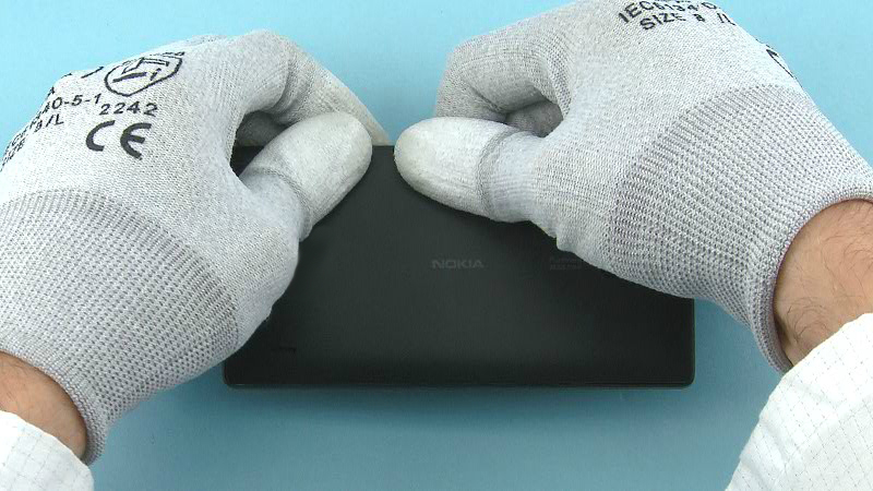
41) Then press together all the other sides of the device to get the BACK COVER completely attached.