Disassembly steps
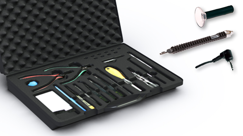
1) For disassembling you need the Nokia Standard toolkit version 2. You will also need the SS-311 back cover release tool, the SS-319 RF-connector disassembly/assembly tool and an AV jack.
Note that the device shown in most of these pictures is the Nokia Lumia Icon. On those steps the spare parts and the disassembly procedures are the same.
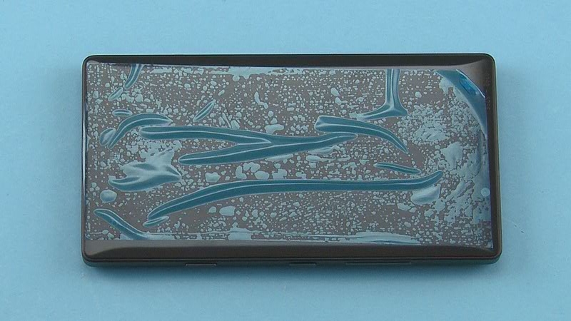
2) Protect the DISPLAY WINDOW with protective film.
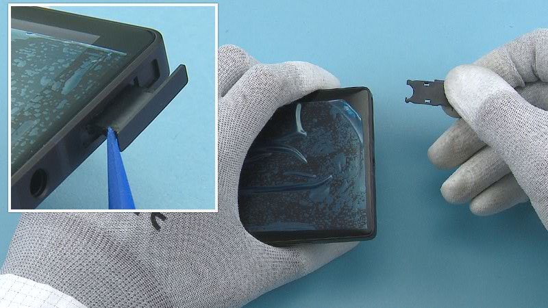
3) Open the SIM TRAY with the SS-93 and pull it out.
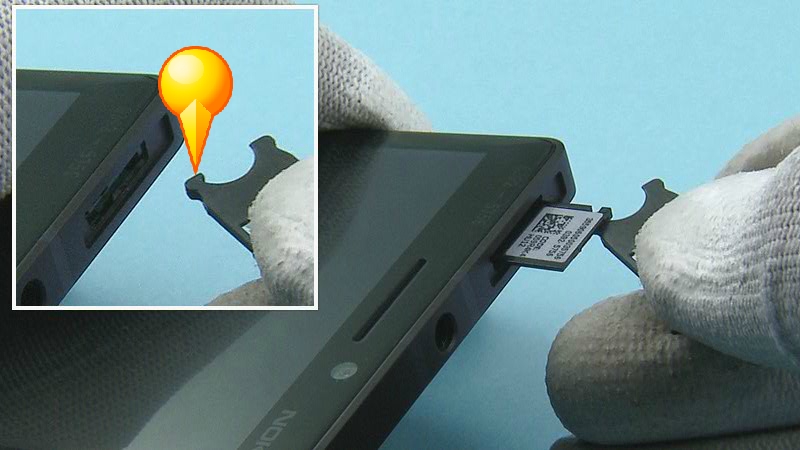
4) At this point, if you only want to check the TYPE LABEL without having to disassemble the phone, you can pull the LABEL TRAY out with the hook on the SIM TRAY.
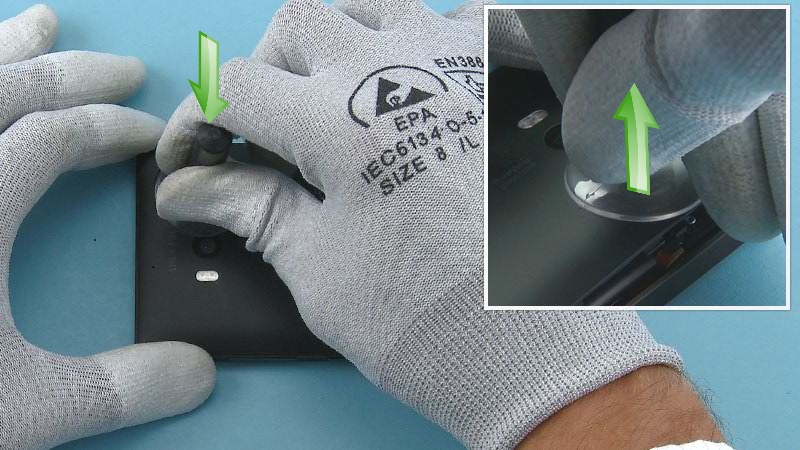
5) Release the BACK COVER with the SS-311 from the shown corner.
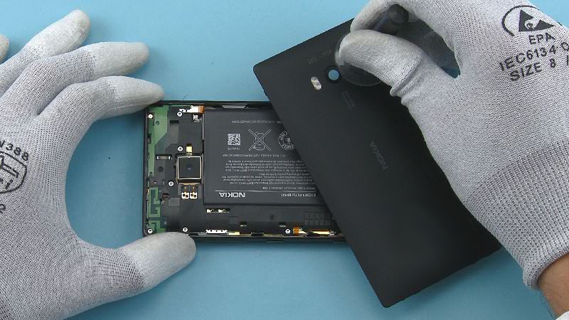
6) Remove the BACK COVER.
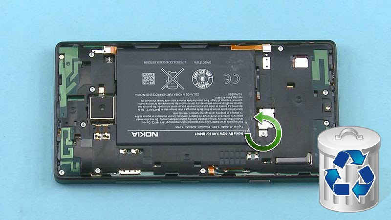
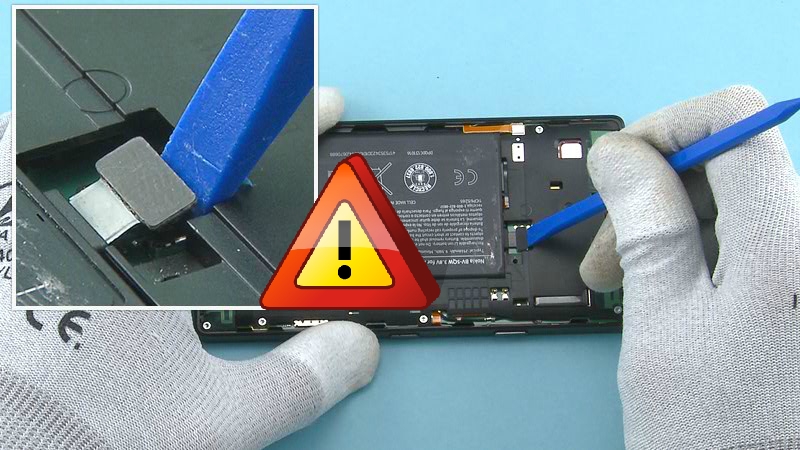
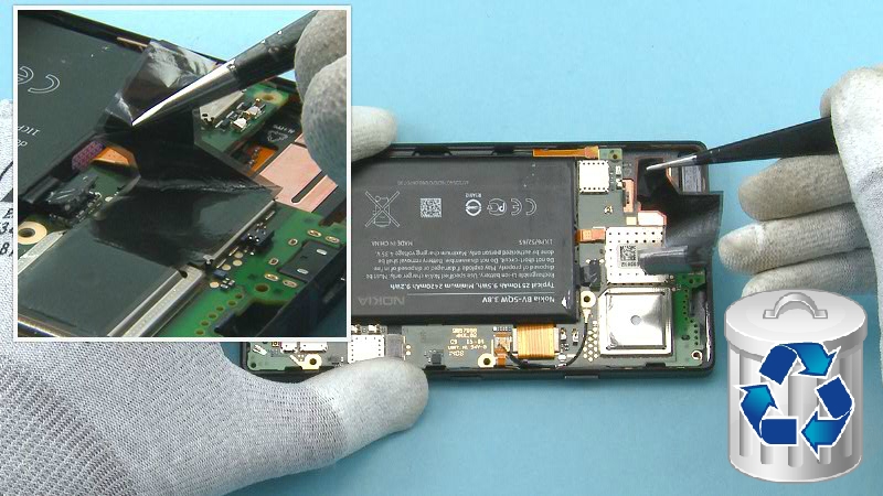
7) Unscrew the TORX+ SIZE 4 screw on top of the BATTERY CONNECTOR STRAP. Do not use the screw again. Discard it.
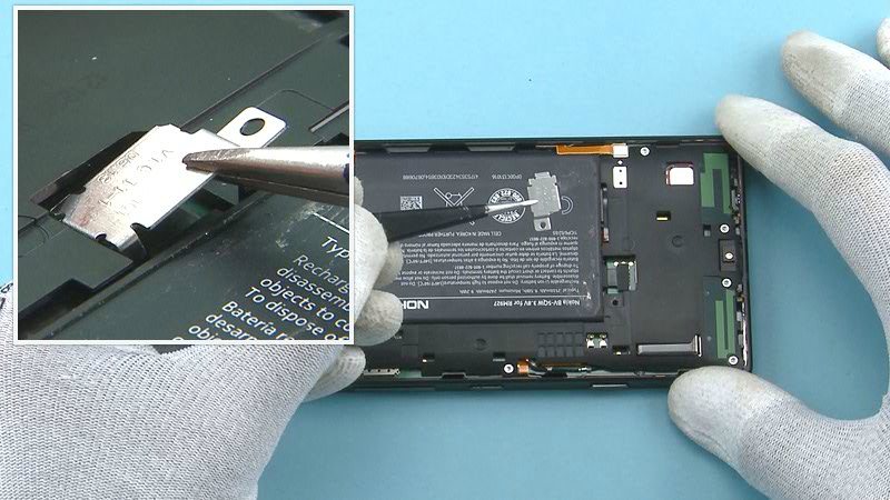
8) Remove the BATTERY CONNECTOR STRAP with tweezers.
9) Disconnect the BATTERY connector with the SS-93. Be careful not to damage the connector.
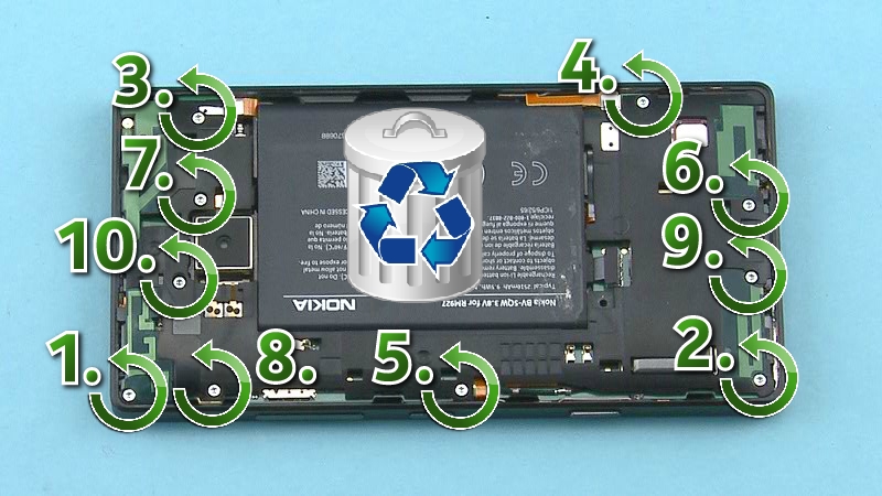
10) Unscrew the ten TORX+ SIZE 4 screws in the order shown. Do not use the screws again. Discard them.
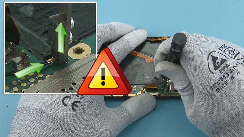
11) Release the ENGINE COVER ASSEMBLY from the shown place with the SS-93.
12) Lift up and remove the ENGINE COVER ASSEMBLY top end first. Be careful not to damage the antenna spring contacts on the bottom of the ENGINE COVER ASSEMBLY.
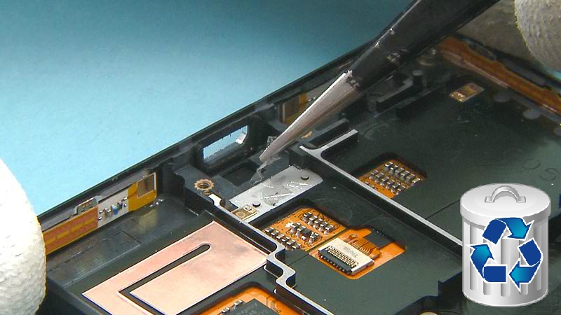
13) Remove the HEAT SPREADER with tweezers. Do not use it again. Discard it.
Note that the HEAT SPREADER needs to be removed completely ONLY when the ENGINE BOARD requires repair work.
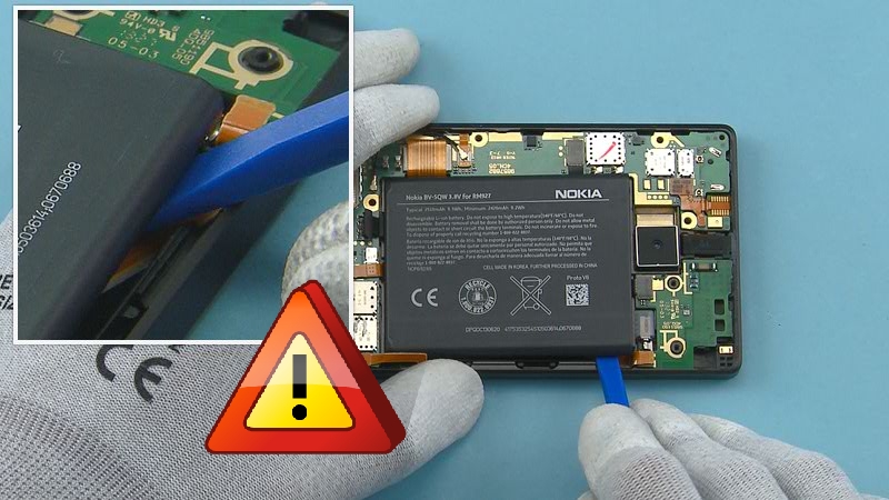
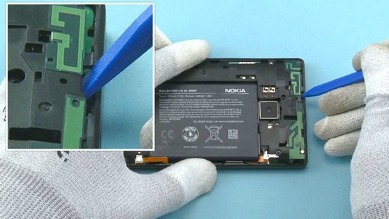
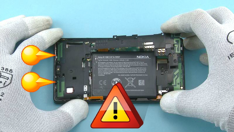
14) Release the BATTERY from the shown place with the SS-93. Be careful not to damage the two flexes located under the BATTERY.
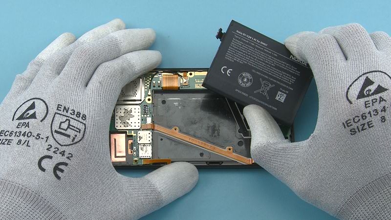
15) Remove the BATTERY.
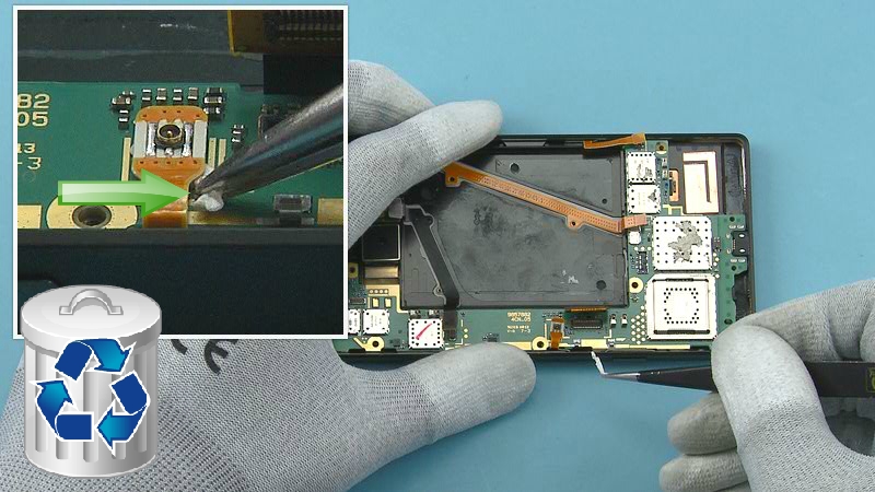
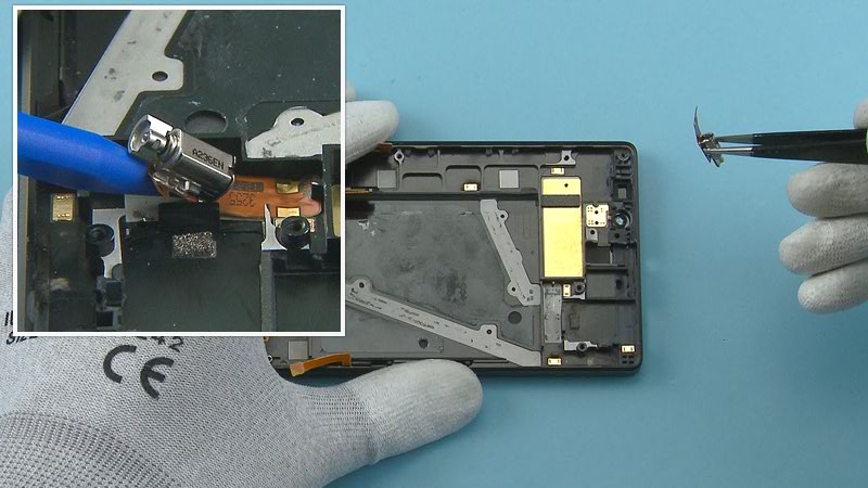
16) Disconnect the SKYPE CAMERA connector from the shown edge with the SS-93. Be careful not to damage the connector or any components nearby.
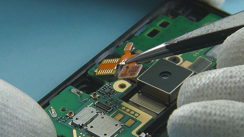
17) Remove the SKYPE CAMERA with tweezers.
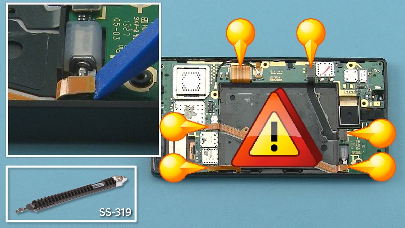
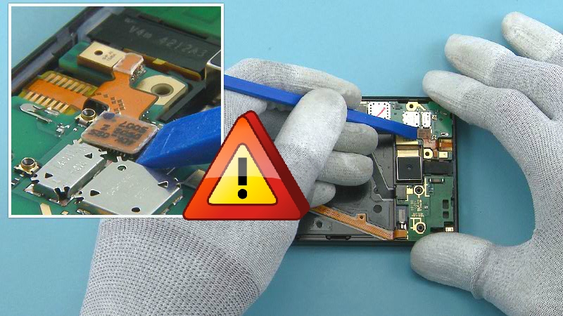
18) Disconnect the six shown connectors with the SS-93. Be careful not to damage the connectors or any components nearby.
Note that the SS-319 can also be used to disconnect the connectors.
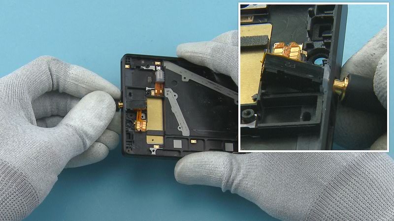
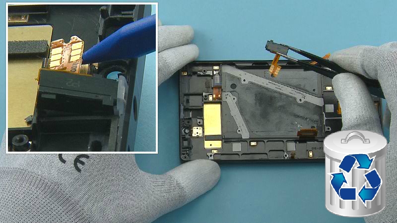
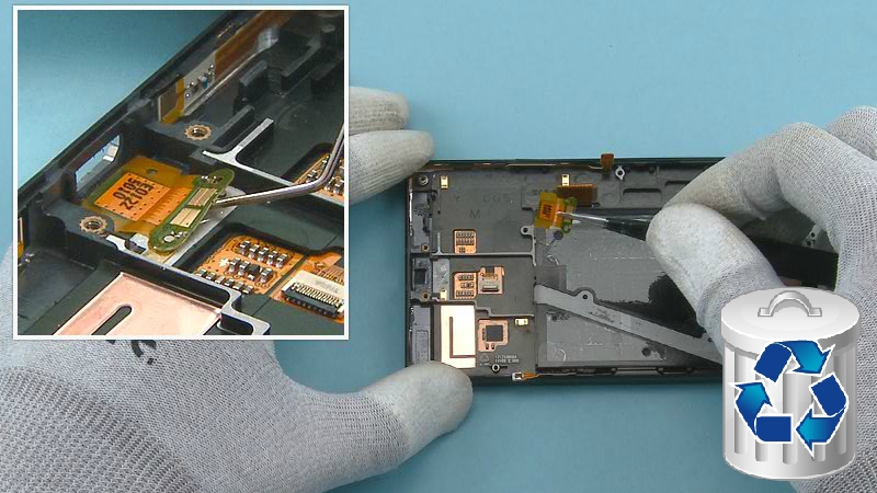
19) Release the RF CABLE connector with the SS-319. Lock the SS-319 to the top of the connector as shown and lift it up carefully. Be careful not to damage the connector.
20) Release also the other end of the RF CABLE and remove it.
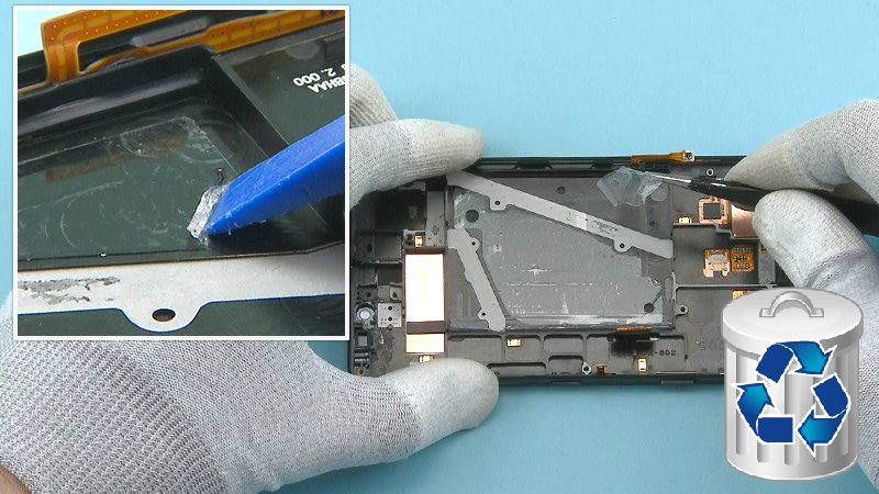
21) Pull the LTE ADHESIVE to the direction shown to remove it under the LTE FLEX. Do not use it again. Discard it.
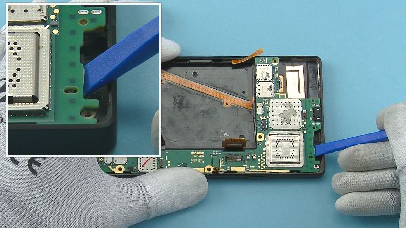
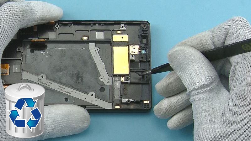
22) Release the ENGINE BOARD from the shown place with the SS-93.
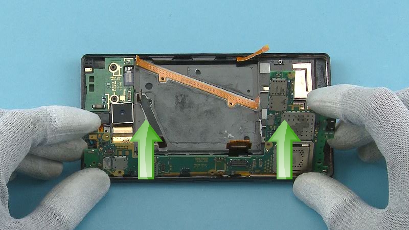
23) Lift up the other side and remove the ENGINE BOARD to the direction shown.
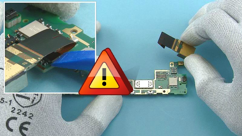
24) Disconnect the CAMERA connector from the shown edge with the SS-93. Be careful not to damage the connector or any components nearby. Remove the CAMERA.
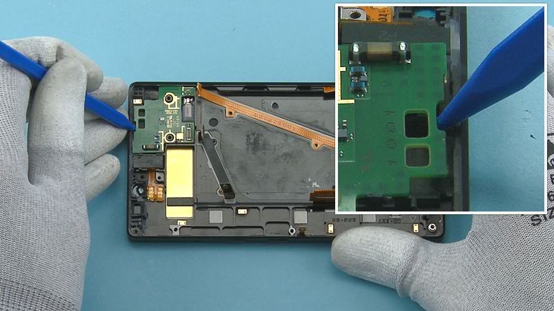
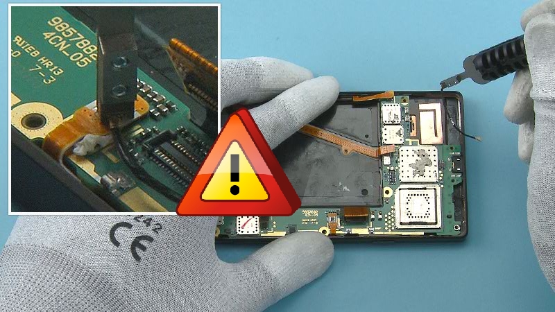
25) Release the DAUGHTER ENGINE BOARD from the shown place with the sharp end of the SS-93.
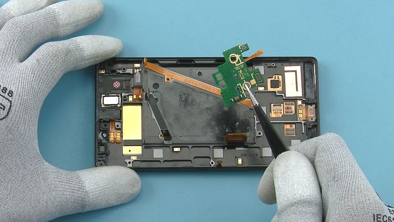
26) Remove the DAUGHTER ENGINE BOARD.
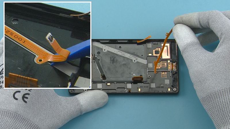
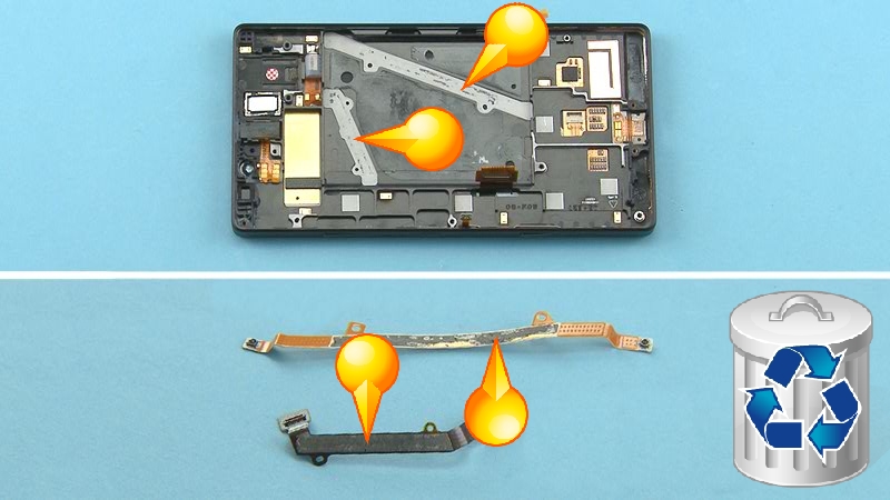
27) Peel off the MIMO COAX FLEX with the SS-93.
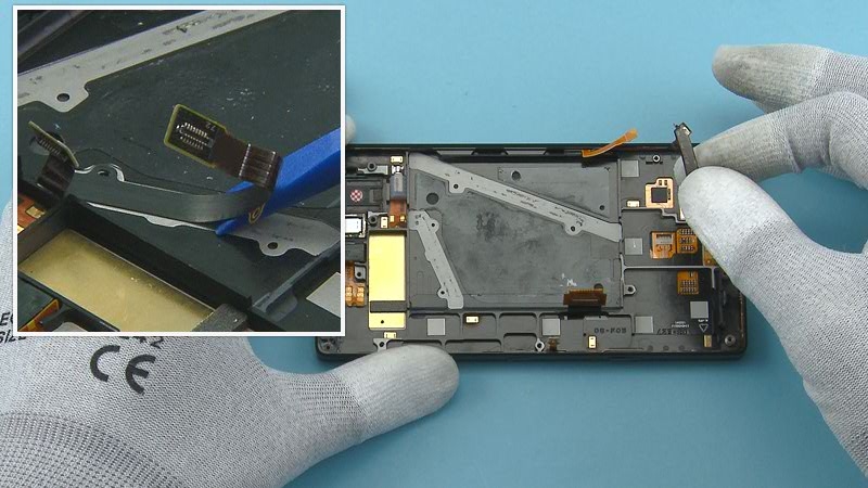
28) Peel off the JUMPER FLEX with the SS-93.
29) If the UI ASSEMBLY or the flexes are being reused, peel off and discard any adhesive residue.
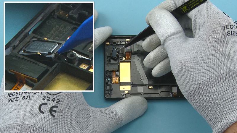
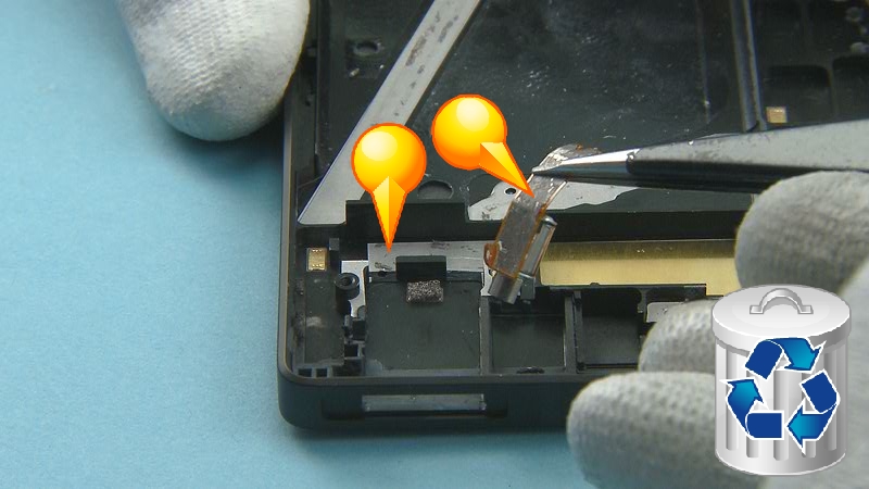
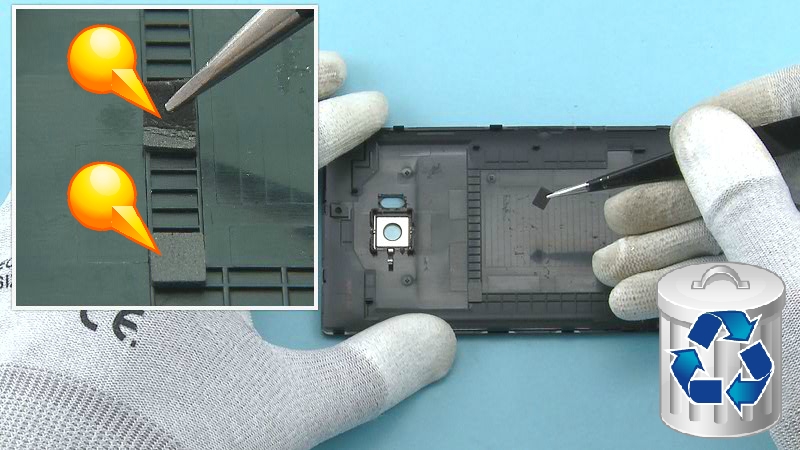
30) Release the EARPIECE with the SS-93 and remove it with tweezers.
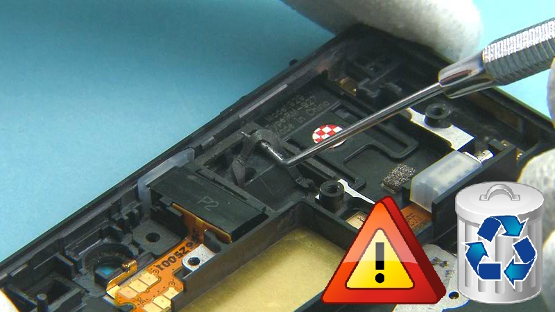
31) Remove and discard the EARPIECE GASKET with the dental tool. Be careful not to injure yourself with the sharp end of the dental tool.
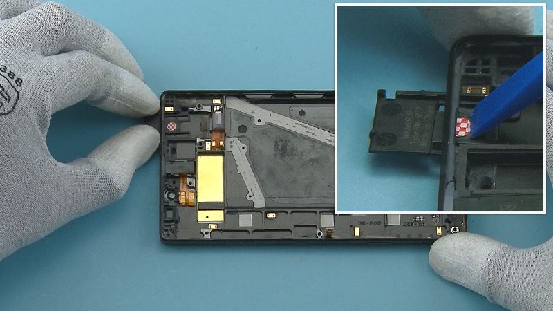
32) Push out the LABEL TRAY with the SS-93 and remove it.
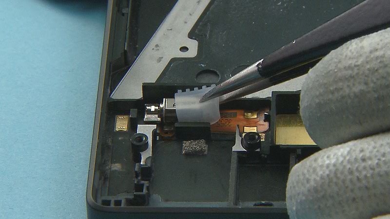
33) Use an AV jack to lift up the HSJ ASSEMBLY.
34) Release the HSJ ASSEMBLY flex with the SS-93 and remove the HSJ ASSEMBLY. Do not use it again. Discard it.
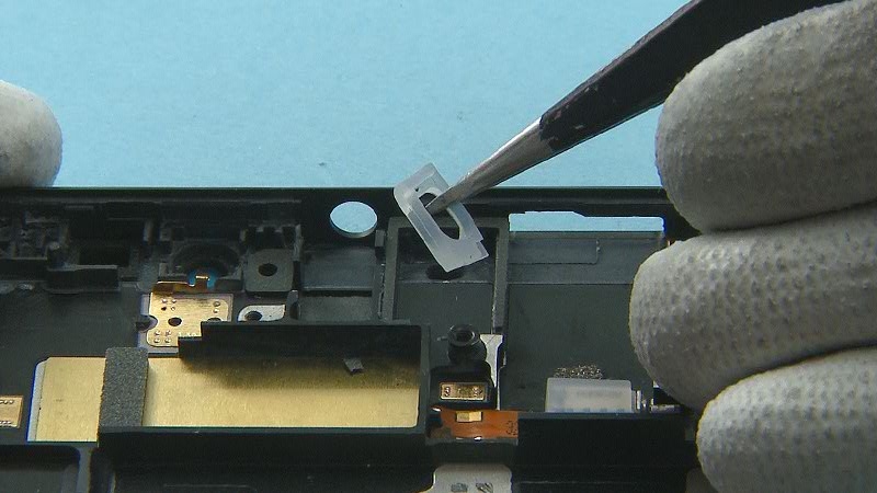
35) Remove the HSJ GASKET with tweezers.
36) Remove the VIBRA BOOT with tweezers.
37) Release the VIBRA and the VIBRA flex with the SS-93. Remove the VIBRA ASSEMBLY.
38) If the UI ASSEMBLY or the VIBRA ASSEMBLY are being reused, remove and discard any adhesive residue.
39) Remove and discard the DAUGHTER ENGINE BOARD GASKET only if it is damaged.
40) Release the PRIMARY MIC FLEX with the dental tool and remove it with tweezers. Do not use it again. Discard it.
41) Remove and discard the PRIMARY MIC FLEX ADHESIVE from the UI ASSEMBLY with tweezers.
42) Peel off and discard the SMALL BATTERY ADHESIVE using SS-93 and tweezers.
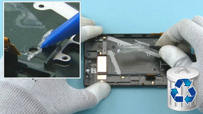
43) Peel off and discard the BATTERY ADHESIVE using SS-93 and tweezers
44) Release the WIRELESS CHARGING ASSEMBLY with the SS-93.
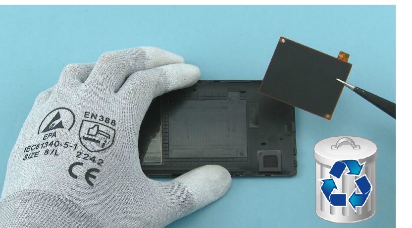
45) Remove the WIRELESS CHARGING ASSEMBLY. Do not use it again. Discard it.
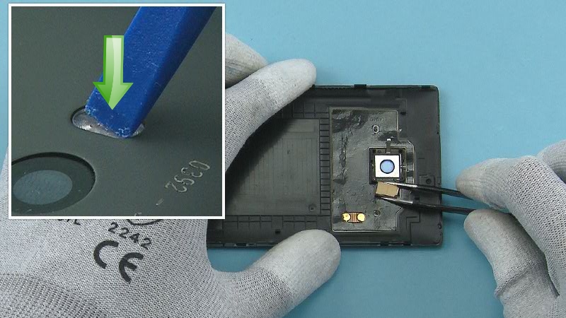
46) Push the LED FLASH from the back side with the SS-93 and remove it with tweezers. Remove any adhesive remains from the LED FLASH.
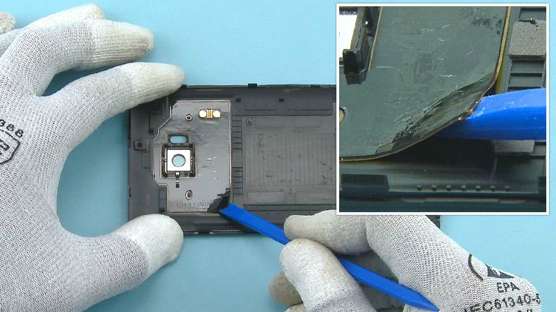
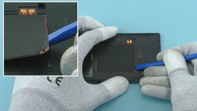
47) Release the NFC ANTENNA with the SS-93. Start from the corner.
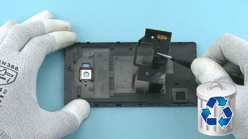
48) Remove the NFC ANTENNA. Do not use it again. Discard it.
49) Remove and discard the two BACK COVER GASKETS with tweezers.
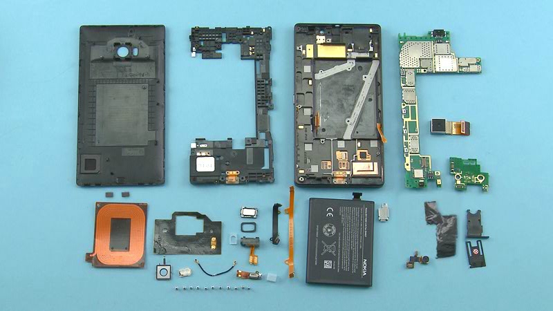
50) The Nokia Lumia 930 disassembly procedure is complete.
-END OF DISASSEMBLY-